Components
- Technical requirements
- Diagrams
- How it’s used
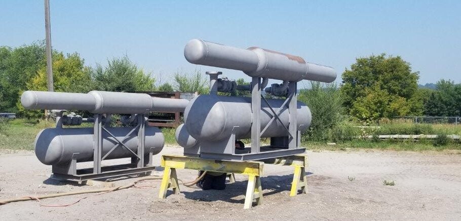
Innopipe Gas Separator System
Overview of gas / liquid removal system
The Innopipe inline Gas Separator and Inline Piggable Drip system has three main components:
- Separator section
- Interconnecting piping
- Collection Vessel
Separator sizes:
1” to 60” Innopipe Gas Separator designed to match pipeline size and grade. Beveled for inline welding or flanged.
Diagrams
Installation below grade with installed cassions
How it’s used
Innopipe – versatile and flexible
The Innopipe inline gas separator and piggable drip system is versatile and flexible and can be designed to meet custom specifications.
The system can be used for sweet or sour gas and adjusted to meet required flow rates. It can be installed in harsh, cold climates without compromising effectiveness. Options for installation include buried below grade, above ground or installed in vaults or cassions.
The system meets all industry design standards.
